HINGED EXPANSION JOINT
The hinged expansion joint (EJ) consists of a bellows element attached to end fittings with hinge hardware traversing the bellows element.
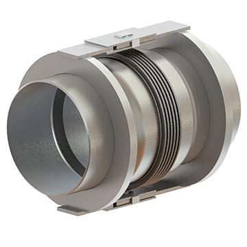
Movement Capabilities
In a single hinge EJ the hardware limits the movement to one degree of freedom, angular deflection about a single axis. The hinge hardware can be designed to contain the pressure thrust that is generated when the expansion joint is pressurized in service. Deflection spring forces must be accommodated by the system designer. The hinge hardware also resists torsion loads and shear forces that may result from adjacent piping.
Features:
- Hinge hardware can contain pressure thrust
- Single hinge EJ has one degree of movement, angular about a single axis
- The three hinge system articulates to handle angular, axial, and lateral offset in a single plane
- Versatile and common throughout all industries
Benefits:
- Hinge hardware protects the bellows element from shear loads and torsion
- Lateral restraint from the hinge hardware increases stability and allows for higher design pressure
- The universal hinge EJ can handle very large lateral offset with a very low spring rate and high deflection capacity
- The three hinge system can accommodate very large axial and lateral movements with a very low spring rate
UNIVERSAL HINGED EXPANSION JOINT
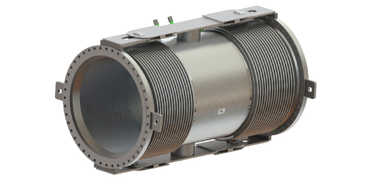
Generally, hinged EJs are used in pairs (universal) or in threes to accommodate large movements. If lateral offset is required a universal hinge EJ is an appropriate choice. In this case there are two bellows elements separated by a center spool with hinge hardware over each bellows element. To accommodate lateral offset each bellows element tilts. The universal hinge EJ can support two degrees of motion, lateral offset in one axis and angular rotation in one axis. The amount of lateral offset is only limited by the distance between the bellows elements and the overall length of the assembly. The separation of the bellows elements also results in a very low lateral offset spring rate. The hinges increase bellows stability which allows for higher design pressures. The hinge hardware also protects the bellows elements from the dead weight of the center spool and torsion loads that could be damaging.
A common design alternative uses a single link to connect the two hinges. In this configuration the thermal growth between the outboard hinge anchor points is imposed on the bellows elements as internal axial movement. That means that the axial growth of the piping between the hinge anchor points can be ignored by the piping designer. This can be a very significant applications issue on high temperature designs and large diameter pipe systems.
When three hinges are used together, large movements in a single plane can be accommodated with very low spring forces. The hinged EJs must be installed in a single plane and the axis of the hinge pins must be perpendicular to that plane. Looking at the three hinge system as single assembly, large axial and lateral piping movements in a single plane can be handled by articulating the three hinges. The movement capabilities are only limited by the available distance between the hinge pins.
Applications:
The hinge EJ is generally applied as a universal or as a three hinge system. Hinged EJs are appropriate for any application where movements are in a single plane and spring forces are a concern. Pressure thrust is contained by the hinge hardware so external anchorage is only required for spring forces. The universal hinge EJ can handle large lateral offsets with low resultant spring forces.
The three hinge system can accommodate very large axial and lateral movements in a single plane with very low spring forces. The low spring force and large movement capability makes the three hinged EJ system an attractive choice for accommodating thermal growth in long pipe runs and for rotating equipment connections that are spring rate sensitive.
Hinged EJs can be provided with U shape convolutions, with or without external reinforcement or control rings, and in toroidally shaped convolutions.
Range of Design & Operating Conditions:
- Full vacuum to 2000 psig depending on size
- Cryogenic to 1600°F
- Sizes from 1” NPS to > 240” NPS
Accessories & Options:
- NDE/QA
- Flow liner
- External cover (Shroud)
- Ply Testable
- Red-Top©
- Multi-Ply Bellows
- Purging
- Insulation
- End Connections
- 2 Ply Test Kit
- On Site Service