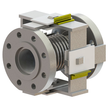
Gimbaled Expansion Joint
The Gimbaled expansion joint (EJ) consists of a bellows element attached to end fittings with gimbal hardware traversing the bellows element.
Movement Capabilities
In a single gimbaled EJ the hardware limits the movement to two degrees of freedom, angular deflection in two axes. The gimbal hardware can be designed to contain the pressure thrust that is generated when the expansion joint is pressurized in service. Deflection spring forces must be accommodated by the system designer. The hinge hardware also resists torsion loads and shear forces that may result from adjacent piping.
Features:
- Gimbal hardware can contain pressure thrust
- Single gimbal EJ has two degrees of movement, angular in two axes
- The universal gimbal configuration has four degrees of movement, angular movement in two axes and lateral offset in two axes
- The two gimbal and one hinge system articulates to handle axial and lateral offset in any plane
- Versatile and common throughout all industries
Benefits:
- Gimbal hardware protects the bellows element from shear loads and torsion
- Lateral restraint from the gimbal hardware increases stability and allows for higher design pressure
- The universal gimbal EJ can handle very large lateral offsets with a very low spring rate
- The universal gimbal EJ can handle very large lateral offsets with a very low spring rate
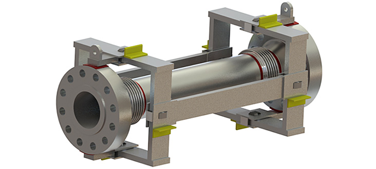
Universal Gimbaled Expansion Joint
Generally, gimbaled EJs are used in pairs (universal) or as gimbal and hinge system that incorporates two gimbaled EJs and one hinged EJ to accommodate large movements. If lateral offset is required a universal gimbal EJ is an appropriate choice. In this case there are two bellows elements separated by a center spool with gimbal hardware over each bellows element. To accommodate lateral offset each bellows element tilts. The universal gimbal EJ can support four degrees of motion, lateral offset in two axes and angular rotation in two axes. The amount of lateral offset is only limited by the distance between the bellows elements and the overall length of the assembly. The separation of the bellows elements also results in a very low lateral offset spring rate.
Applications:
The unrestrained EJ is appropriate for any application where pressure thrust can be handled by external anchorage. The universal unrestrained EJ is appropriate for large lateral offset requirements and wherever a low lateral offset spring rates is required.
Range of Design & Operating Conditions:
- Full vacuum to 2000 psig depending on size
- Cryogenic to 1600°F
- Sizes from 1” NPS to > 240” NPS
Accessories & Options:
- NDE/QA
- Flow liner
- External cover (Shroud)
- Tie rods/Limit rods/Control rods
- Hinge/Slotted Hinge
- Gimbal
- Ply Testable
- Red-Top©
- Multi-Ply Bellows
- Purging
- Insulation
- End Connections
- 2 Ply Test Kit
- On Site Service