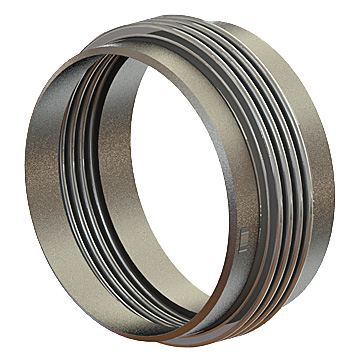
Metal Expansion Joints
Pathway specializes in custom-engineered expansion joints used in critical applications throughout the world.
We are recognized as the lead innovator for high temperature industrial expansion joint applications such as Fluid Catalytic Cracking, Catofin® process, and styrene monomer production.
We also provide a full line of expansion joint products for steam and hot and chilled water piping, compressed air, turbine exhaust, and all other industrial piping and ducting applications.
- Sizes ranging from 2” through 240”
- Cryogenic testing capability
- Cycle life testing & Spring rate testing
- Refractory lining
- Heavy lift and handling capability
- Expanding mandrel and hydraulic bellows forming
- Wide range of material choice
- Expedited delivery
- Warranties you can depend on
Click here for more information about how a Metal Expansion Joint works…
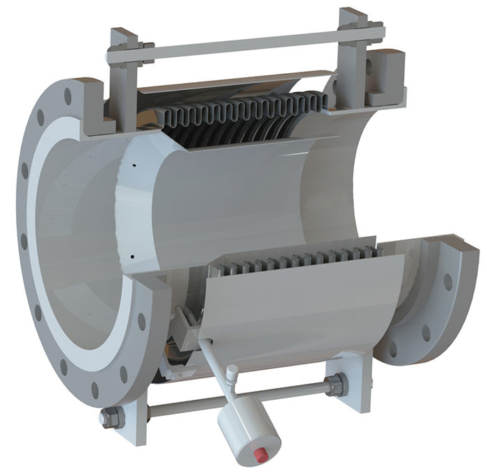
Unrestrained Expansion Joint
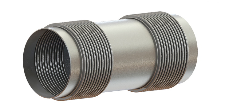
The unrestrained expansion joint (EJ) is simply a bellows element attached to end fittings used to handle movements resulting thermal expansion or contraction of the adjacent piping. The single unrestrained expansion joint is the most basic Expansion Joint type, and can be used as the starting point once the need for an EJ has been established.
It is the most economical EJ product. However, the unrestrained EJ imposes pressure thrust force and deflection spring forces on adjacent anchorage and those forces must be accommodated by the system designer. Also, the amount of lateral offset is limited by the bellows length and often times the bellows length is severely limited by column stability.
Movement Capabilities
The single unrestrained EJ has one bellows element designed to handle five degrees of motion including axial extension and compression, lateral offset in any direction, and angular movements imposed by the adjacent pipe or ducting. It is not intended to handle torsion.
Features:
- Simplest, most economical design
- Accepts axial, lateral, angular movements
- The universal EJ can be designed with a very low lateral spring rate, and high movement capacities
- Versatile and common throughout all industries
Benefits:
- Low Cost
- Handles all types of movement
- Assurance: successful track record in countless applications
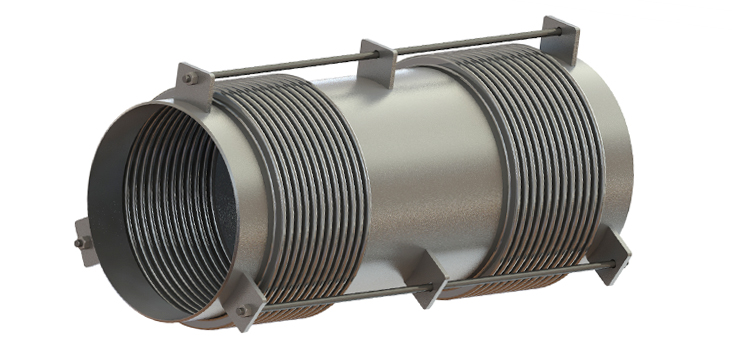
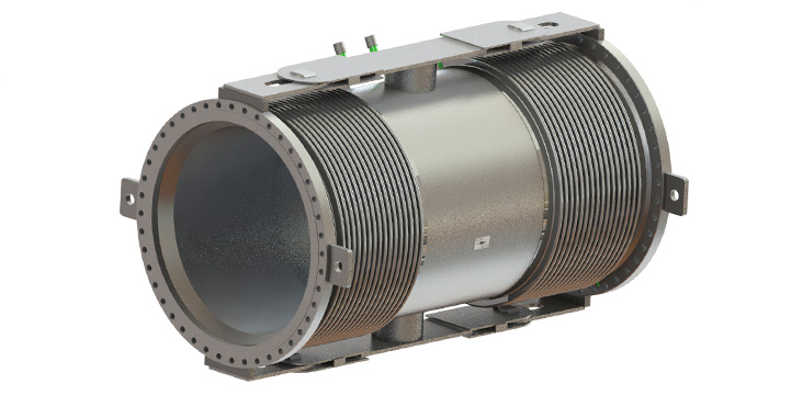
Universal Unrestrained Expansion Joint
If the lateral offset requirement is large, a universal unrestrained EJ is appropriate. The universal EJ has two identical bellows elements that handle lateral offset by tilting of the bellows element rather than shearing. So the individual bellows elements can be quite short and, therefore, stable while handling large lateral offsets.
The amount of lateral offset that can be accommodated is only limited by the distance between the bellows elements and the overall length of the assembly. The separation of the bellows elements also results in a very low lateral offset spring rate. Just like the single, the unrestrained universal EJ imposes pressure thrust forces on adjacent anchors
Applications:
The unrestrained EJ is appropriate for any application where pressure thrust can be handled by external anchorage. The universal unrestrained EJ is appropriate for large lateral offset requirements and wherever a low lateral offset spring rates is required.
Range of Design & Operating Conditions:
- Full vacuum to 2000 psig depending on size
- Cryogenic to 1600°F
- Sizes from 1” NPS to > 240” NPS
Accessories & Options:
- NDE/QA
- Flow liner
- External cover (Shroud)
- Tie rods/Limit rods/Control rods
- Hinge/Slotted Hinge
- Gimbal
- Ply Testable
- Red-Top©
- Multi-Ply Bellows
- Purging
- Insulation
- End Connections
- 2 Ply Test Kit
- On Site Service
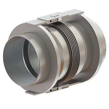
Tied Expansion Joints
Single Tied Expansion Joint
The tied expansion joint (EJ) consists of a bellows element attached to end fittings with threaded rod or bar hardware traversing the bellows element. The tie rods are attached to lugs or rings that limit the length of the EJ. The tie rods and the attachment hardware are designed to contain pressure thrust.
Tied expansion joints are designed to have a fixed overall length. The tie rods are attached in a way that eliminates axial movement and forces the ends of the EJ to remain parallel at all times. This configuration allows for only two degrees of freedom, lateral in two axes.
Movement Capabilities
In a single tied EJ the hardware generally limits the movement to two degrees of freedom, lateral deflection in two axes. The tie rods and hardware are designed to contain pressure thrust so external main anchors are not required. However, deflection spring forces must be accommodated by the system designer.
There is a special configuration that uses just two tie rods. This configuration allows for three degrees of movement, lateral in two axes and angular about one axis.
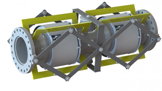
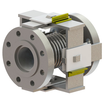
Universal Tied Expansion Joint
If a large lateral offset is required a tied universal EJ is an appropriate choice. In this case there are two identical bellows elements separated by a center spool with tie rod hardware traversing both bellows elements. To accommodate lateral offset each bellows element tilts. The tied universal EJ can support two degrees of motion, just like the tied single EJ.
The amount of lateral offset is only limited by the distance between the bellows elements and the overall length of the assembly. The separation of the bellows elements also results in a very low lateral offset spring rate.
As with the single tied EJ, if just two tie rods are used, the configuration allows for three degrees of movement, lateral in two axes and angular about one axis.
Features of Tied Design:
- Simple design, Relatively low cost
- The universal configuration can be designed with a very low lateral spring rate and high lateral movement capacity
- Versatile and common throughout all industries
- Two degrees of movement capability for tied single or universal design
- Three degrees of movement for two tie rod design
- Tie rods contain pressure thrust
Benefits of tied design:
- Pressure thrust is accommodated by hardware, external anchorage is only required for spring forces
- Can be designed with very low lateral spring rate
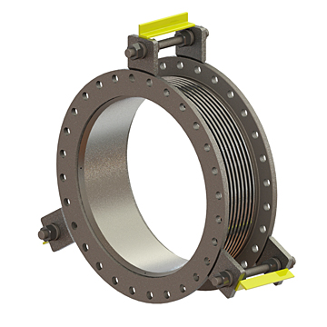
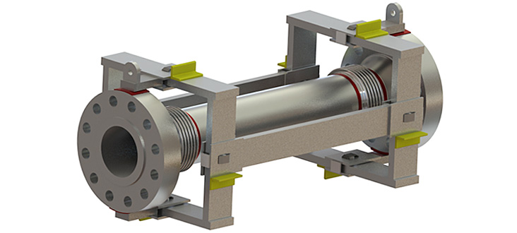
Universal Tied Expansion Joint with Limit Rods
In some cases it is useful to limit the length of an EJ while allowing it to accept axial compression and angular movement in addition to lateral offset. This is called an EJ with limit rods. In the single and universal designs, the EJ with limit rods can accommodate angular movement, just like an unrestrained EJ.
Even though the hardware is designed to contain pressure thrust, the system designer must accommodate pressure thrust with external anchorage if axial movements are applied. As soon as the expansion joint begins to compress or tilt, pressure thrust will no longer be handled by the tie rod hardware.
Features of Limit Rod Design:
- Simple design, Relatively low cost
- The universal configuration can be designed with a very low lateral spring rate and high lateral movement capacity
- Versatile and common throughout all industries
- Five degrees of movement capability for single or universal design
- Tie rods and hardware are designed for pressure thrust but external anchorage is required to contain spring forces and pressure thrust in service
Benefits of Limit Rod Design:
- Hardware is can be relied upon to contain pressure thrust in the event of failure of a piping anchor
- Can be designed with very low lateral spring rate
Applications:
The Tied EJ is appropriate for any application where movement can be limited to lateral offset in two axes. Since pressure thrust is handled by the tie rod hardware, external anchorage is only required to handle spring forces. Where very low lateral spring rate is required, the tied universal configuration is the best solution.
It is also worth noting that the thermal growth between the tie rod anchor points is imposed on the bellows elements as internal axial movement.
That means that the axial growth of the piping between the tie rod anchor points can be ignored by the piping designer. This can be a very significant applications issue on high temperature designs and large diameter pipe systems.
The limit rod EJ is appropriate for any application that could accommodate an unrestrained expansion joint. However, since the limit rod hardware is designed for pressure thrust, the limit rods act as insurance, a safety backup, against loss of external anchorage.
Range of Design & Operating Conditions:
- Full vacuum to 2000 psig depending on size
- Cryogenic to 1600°F
- Sizes from 1” NPS to > 240” NPS
Accessories & Options:
- NDE/QA
- Flow liner
- External cover (Shroud)
- Tie rods/Limit rods/Control rods
- Hinge/Slotted Hinge
- Gimbal
- Ply Testable
- Red-Top©
- Multi-Ply Bellows
- Purging
- Insulation
- End Connections
- 2 Ply Test Kit
- On Site Service
Hinged Expansion Joint
The hinged expansion joint (EJ) consists of a bellows element attached to end fittings with hinge hardware traversing the bellows element.
Movement Capabilities
In a single hinge EJ the hardware limits the movement to one degree of freedom, angular deflection about a single axis. The hinge hardware can be designed to contain the pressure thrust that is generated when the expansion joint is pressurized in service. Deflection spring forces must be accommodated by the system designer. The hinge hardware also resists torsion loads and shear forces that may result from adjacent piping.
Features:
- Hinge hardware can contain pressure thrust
- Single hinge EJ has one degree of movement, angular about a single axis
- The three hinge system articulates to handle angular, axial, and lateral offset in a single plane
- Versatile and common throughout all industries
Benefits:
- Hinge hardware protects the bellows element from shear loads and torsion
- Lateral restraint from the hinge hardware increases stability and allows for higher design pressure
- The universal hinge EJ can handle very large lateral offset with a very low spring rate and high deflection capacity
- The three hinge system can accommodate very large axial and lateral movements with a very low spring rate
Universal Hinged Expansion Joint
Generally, hinged EJs are used in pairs (universal) or in threes to accommodate large movements. If lateral offset is required a universal hinge EJ is an appropriate choice. In this case there are two bellows elements separated by a center spool with hinge hardware over each bellows element. To accommodate lateral offset each bellows element tilts. The universal hinge EJ can support two degrees of motion, lateral offset in one axis and angular rotation in one axis. The amount of lateral offset is only limited by the distance between the bellows elements and the overall length of the assembly. The separation of the bellows elements also results in a very low lateral offset spring rate. The hinges increase bellows stability which allows for higher design pressures. The hinge hardware also protects the bellows elements from the dead weight of the center spool and torsion loads that could be damaging.
A common design alternative uses a single link to connect the two hinges. In this configuration the thermal growth between the outboard hinge anchor points is imposed on the bellows elements as internal axial movement. That means that the axial growth of the piping between the hinge anchor points can be ignored by the piping designer. This can be a very significant applications issue on high temperature designs and large diameter pipe systems.
When three hinges are used together, large movements in a single plane can be accommodated with very low spring forces. The hinged EJs must be installed in a single plane and the axis of the hinge pins must be perpendicular to that plane. Looking at the three hinge system as single assembly, large axial and lateral piping movements in a single plane can be handled by articulating the three hinges. The movement capabilities are only limited by the available distance between the hinge pins.
Applications:
The hinge EJ is generally applied as a universal or as a three hinge system. Hinged EJs are appropriate for any application where movements are in a single plane and spring forces are a concern. Pressure thrust is contained by the hinge hardware so external anchorage is only required for spring forces. The universal hinge EJ can handle large lateral offsets with low resultant spring forces.
The three hinge system can accommodate very large axial and lateral movements in a single plane with very low spring forces. The low spring force and large movement capability makes the three hinged EJ system an attractive choice for accommodating thermal growth in long pipe runs and for rotating equipment connections that are spring rate sensitive.
Hinged EJs can be provided with U shape convolutions, with or without external reinforcement or control rings, and in toroidally shaped convolutions.
Range of Design & Operating Conditions:
- Full vacuum to 2000 psig depending on size
- Cryogenic to 1600°F
- Sizes from 1” NPS to > 240” NPS
Accessories & Options:
- NDE/QA
- Flow liner
- External cover (Shroud)
- Ply Testable
- Red-Top©
- Multi-Ply Bellows
- Purging
- Insulation
- End Connections
- 2 Ply Test Kit
- On Site Service
Gimbaled Expansion Joint
The Gimbaled expansion joint (EJ) consists of a bellows element attached to end fittings with gimbal hardware traversing the bellows element.
Movement Capabilities
In a single gimbaled EJ the hardware limits the movement to two degrees of freedom, angular deflection in two axes. The gimbal hardware can be designed to contain the pressure thrust that is generated when the expansion joint is pressurized in service. Deflection spring forces must be accommodated by the system designer. The hinge hardware also resists torsion loads and shear forces that may result from adjacent piping.
Features:
- Gimbal hardware can contain pressure thrust
- Single gimbal EJ has two degrees of movement, angular in two axes
- The universal gimbal configuration has four degrees of movement, angular movement in two axes and lateral offset in two axes
- The two gimbal and one hinge system articulates to handle axial and lateral offset in any plane
- Versatile and common throughout all industries
Benefits:
- Gimbal hardware protects the bellows element from shear loads and torsion
- Lateral restraint from the gimbal hardware increases stability and allows for higher design pressure
- The universal gimbal EJ can handle very large lateral offsets with a very low spring rate
- The universal gimbal EJ can handle very large lateral offsets with a very low spring rate
Universal Gimbaled Expansion Joint
Generally, gimbaled EJs are used in pairs (universal) or as gimbal and hinge system that incorporates two gimbaled EJs and one hinged EJ to accommodate large movements. If lateral offset is required a universal gimbal EJ is an appropriate choice. In this case there are two bellows elements separated by a center spool with gimbal hardware over each bellows element. To accommodate lateral offset each bellows element tilts. The universal gimbal EJ can support four degrees of motion, lateral offset in two axes and angular rotation in two axes. The amount of lateral offset is only limited by the distance between the bellows elements and the overall length of the assembly. The separation of the bellows elements also results in a very low lateral offset spring rate.
A common design alternative uses a single link to connect the two gimbals. In this configuration the thermal growth between the outboard gimbal anchor points is imposed on the bellows elements as internal axial movement. That means that the axial growth of the piping between the gimbal anchor points can be ignored by the piping designer. This can be a very significant applications issue on high temperature designs, large diameter pipe systems, and systems that are spring rate sensitive.
Applications:
The unrestrained EJ is appropriate for any application where pressure thrust can be handled by external anchorage. The universal unrestrained EJ is appropriate for large lateral offset requirements and wherever a low lateral offset spring rates is required.
Range of Design & Operating Conditions:
- Full vacuum to 2000 psig depending on size
- Cryogenic to 1600°F
- Sizes from 1” NPS to > 240” NPS
Accessories & Options:
- NDE/QA
- Flow liner
- External cover (Shroud)
- Tie rods/Limit rods/Control rods
- Hinge/Slotted Hinge
- Gimbal
- Ply Testable
- Red-Top©
- Multi-Ply Bellows
- Purging
- Insulation
- End Connections
- 2 Ply Test Kit
- On Site Service

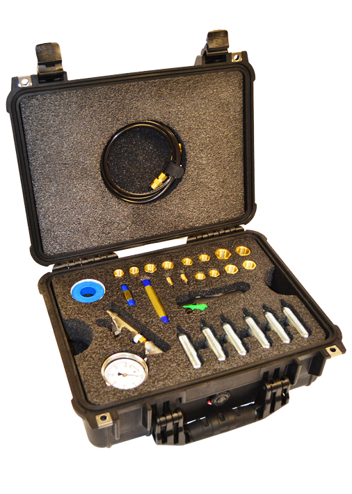
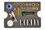
A two ply bellows element should be routinely tested to confirm that both the inner and outer plys are operating properly.
Testing to confirm there is no leak in either ply or the two attachment welds is the best way to avoid bellows failure and costly shut downs.
Senior Flexonics Pathway has a long history of supply of ply testable expansion joints for critical service. As part of our product support our field teams have performed ply tests in facilities all over the world. We’ve used that knowledge in creating this kit, and we know that you’ll find it to be invaluable when performing ply tests in your facility.
Kit Price: $995